The licences held by mobile phone operators are often require them to achieve a percentage of signal coverage in a certain time. They then often publish coverage maps that show they have achieved almost complete coverage in their licence area. This is usually as high as 90-95% of coverage area. However everyone experiences dropped calls or very poor to non-existent data speeds more frequently than coverage maps would indicate should occur. The reason is the coverage maps refer to outdoor signal level, not the signal level experienced indoors or in vehicles. Double glazing, foil backed insulation, thick stone or concrete walls all reduce indoor signal levels, often to the
point that mobile devices have very poor or no indoor signal. The situation is not helped by the fact that the antennas in smart phones, USB sticks etc. are not very efficient. The antenna designers would prefer to have a physically larger antenna, similar to the antennas used many years ago in early mobile phones, but the physical size and form factor of smart phones, USB sticks etc do not allow the use of such large antennas. I think everyone remembers experiencing more dropped phone calls, after upgrading from their old Nokia to a smartphone.
Another reason is the fact that the power of the signal transmitted by the base station is often more than 10 watts, but your mobile phone is limited to a transmit power of less
than 1W. This is a difference of 10dB. So in many cases there may be reasonably good downlink signal strength, so that your phone can “hear” the base station, but due to the limited transmit power of your mobile phone, the base station can’t “hear” your phone when it tries to communicate back to the base station. Everyone has experienced looking at their phone, seeing 1 or 2 signal bars, trying to make a call and not being able to, looking back at their phone in surprise and annoyance and seeing no signal bars. This is a very good example of your phone being able to “hear” the basestation, but as soon as it trys to communicate back to the base station (due to your call), realises it can’t be heard. The signal bar algorithm quickly takes this into account and removes all signal bars.
The solution is to capture the good outdoor signal using a reasonably good antenna, amplify this good signal with a good repeater, and re-broadcast the powerful signal into the indoor environment.
Drawing of this.
Description of drawing.
While all this seems straight forward, a poorly designed repeater can cause severe problems to the operators network. There are three main problems but the causes and solutions to these problems are well understood (though unfortunately not applied in many repeater designs!) .
1). If the indoor and outdoor antenna are placed too close together, the some of the amplified signal transmitted by one antenna can leak back into the other antenna and get “re-amplified”. This creates an “oscillation”. This is a high power signal tone that can be transmitted by the outdoor antenna up to the base station, or by the indoor antenna into the indoor coverage area. It will de-sensitise the base stations ability to “hear” other mobile phone users. The mobile phone operator and the Telecom regulator will not be happy with this, and will make great efforts to find the offending repeater.
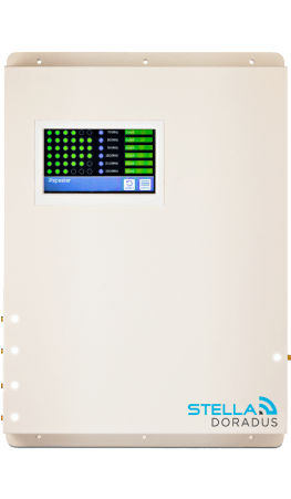
Solution: A well designed repeater will have “intelligence” build in. It will be able to make the distinction between mobile phone signals and an oscillation signal, and react such that the oscillation ceases. Stelladoradus repeaters constantly monitor the type of signals passing through them, and will automatically reduce the gain of the repeater to the level where the oscillation ceases. This means that irrespective of how the repeater is installed, an oscillation can’t occur for more than a few seconds after switch on. An orange LED light for a few seconds, advising the installer that this has occurred. This is not serious, but if the installer wants to take full advantage of the gain of the repeater, they should increase the physical separation between the indoor and outdoor antennas, and cycle the power to the repeater. Cycling the power to the repeater re-sets the amplifier gains of the repeater
2). All amplifiers generate “noise”. This is a low level unwanted broadband signal. The noise level is proportional to the gain of the amplifier. (for a more complete description of noise, please read ———-). So, the repeater will be transmitting noise through the outdoor antenna up to the base station, 24 hours a day, as long as the repeater is powered on. If the repeater is installed far away from the operators base station, this will not be much of a problem, but if it is close, it will de-sensitise the base stations ability to hear other mobile phone users. If there are many repeaters installed in the area, their noise levels will combine, making the base station de-sensitisation problem worse.
Solution: While noise will be transmitted both by the outdoor antenna up to the base station and the indoor antenna into the indoor coverage area, it is the noise up to the base station that is most serious. A solution is to reduce the uplink gain of the repeater unless the repeater is actually transmitting an uplink signal. All Stelladoradus repeaters have a switch mechanism whereby the uplink gain of the repeater is normally close to
zero, (meaning no noise generation) until an uplink signal is detected. When an uplink signal is detected, the switch changes state in less than 1 microsecond, and the full uplink gain of the repeater is applied to the uplink signal. The switch reverts to it’s original state a few seconds after the last uplink signal is detected. LEDs on the front panel of the repeaters indicate all this. An orange LED lights a few seconds after the repeater is initially powered on, indicating there is no uplink signal detected. As soon as an uplink signal is detected (a phone call is being made, or internet browsing is occurring), the orange LED goes out, and a green LED lights. The situation reverses after the last uplink signal is detected. Stelladoradus has applied for a patent for aspects of this invention.
3). All RF semiconductor devices are subject to “compression” if too high a signal level is injected into them. This is especially true of amplifiers. An amplifier is supposed to faithfully re-produce the signal that is input into it, but at a higher power. If compression occurs, the amplifier will also produce other unwanted signals. If these unwanted signals are at a high enough level, they will again de-sensitise the base station. So a badly designed repeater will amplify your mobile phone signals, but can also produce compression products.
Solution. Automatic gain control must be designed into the repeater. This means the gain of the repeater is temperarily reduced if the input signal into the repeater is too high. After the high power signal level ceases, the gain of the repeater should revert to normal. The built in intelligence in the repeater should take care of this, and distinguish between high power “oscillation” signals, where the gain of the repeater should be permanently reduced, and high power “valid mobile device” signals where the gain of the repeater should temporarily reduced.
Some repeaters on the market lack some or all of the protection features described above. Some of those have features like manual gain control in an attempt to reduce the problems described above. This leaves it to the installer and user to carefully adjust the uplink and downlink gains of the repeater to ensure oscillations don’t occur, uplink noise levels are low enough not to interfere with the operators base station, and the gain of the
repeater is low enough so that compression does not occur. However, it would take a skilled RF engineer with a very expensive spectrum analyser to do this effectively, and still have enough gain to substantially improve indoor coverage. Even then, he could not check the effects of uplink noise on the base station, and he would have to excessively reduce the gain of the repeater to ensure compression in the amplifiers did not occur in any situation.
The built in intelligence in Stelladoradus repeaters automatically adjust both uplink and downlink gain, switch off the uplink gain when not in use (which is usually most of a 24 hour day), and monitor and adjust for oscillations 100’s of times a second while the repeater is powered on, automatically ensuring the repeater operates at maximum possible performance while protecting the operators network, all without any input from the user.
James Browne
Stella Doradus CEO


